—=== Understanding G80 behavior and performances ===—
Cyril Crassin, Fabrice Neyret LJK-INRIA, Grenoble, France
http://www-evasion.imag.fr/GPU/CN08
This is an evolving document (corrections, additions): please link it, but don’t copy it !
This is also an open document and we hope to engage discussions on the forum here.
version: March, 8 2008
|
|
|
 |
Index :
1. Motivations
2. Summary of our discoveries
3. Methodology
4. Experiments
5. Recommendations
1. Motivations

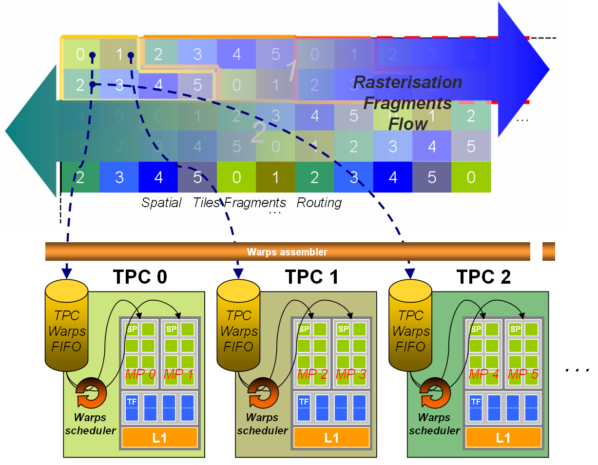
(See Figure 4 for the general organization).
- The rasterizer allocates fragments to texture processors (pairs of multiprocessors) based on the location on screen: screen is subdivided in tiles of size 16×16 which are bounds to TPs according to a fix pattern (see Figure 3).
- For one given TP, the flow of fragments is assembled in warps of 32 threads then stored in a FIFO.
- Warps of one FIFO are executed by any of the two MPs of the TP.
- Threading can use shader wait-states (texture access, transcendent maths, pipeline dependencies) to run some warps partly in parallel on the same MP.
- In the general case, warp fragments are not geometrically ordered and can correspond to any location within the screen footprint of a TP (see Figure 6).
- In facts, fragments are managed in groups of 2×2 (4×2?) “superfragments”. In particular, points, lines and triangle borders yield some waste since “ghost fragments” are generated to fill superfragments and are treated as regular threads (with no output).
- For unknown reason, only 4 isolated points or primitives of size 1 can fit a warp (8 were expected).
- If one FIFO is full the rasterizer has to wait, which might starve the other TPs (see Figure 2).
3. Methodology
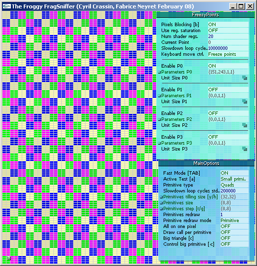
We wrote a small probe program “fragSniffer”allowing us to trigger various configuration tests providing 2 kinds of outputs:
- Showing fragment writing order into the front-buffer, comprising locks, stalls, synchronizations.
- Measuring performance changes when changing configuration parameters.
The principle is to use very slow fragment shaders (doing simple additions into a user controlled loop, typically 10^6 iterations). In particular, some of our fragment shaders get slow only for one pixel on screen, or for a couple of pixels. In case of several slow pixels, these can run either the same shader instructions or 2 different branches of a conditional statement. Speed, number of slow pixels and their location, as well as speed of “background fragments” can all be controlled manually.
Tested configurations concern the pattern and relative location of slow pixels, and also the type of primitive drawn on screen: large or small, stripped or not, 2D,1D or 0D, traced in smart, raster or shuffle order, tiling the screen or overlapping. Note that due to the use of extremely slow shaders, the cost of CPU, bus transfer and vertex transform is negligible.
Our probe tool fragSniffer is freely available here: FragSniffer_0.2.zip
The board used for our experiments was a 8800 GTS: it has 96 Stream processors (SP), grouped by 8 working in SIMD into 12 Multi Processors (MP), which are paired as 6 Texture Processors (TP). Threads are scheduled on Multi Processors into Warps of 32 threads executed in SIMD (within 4 cycles) on the 8 SPs of the MP (see CUDA manual for more details).
We also run our probe on other boards, e.g. a 8600M GT having 16 SP grouped into 4 MP =2 TP just to verify that results were consistent.
Disclaimer:
The G80 is a quite complex ecosystem we tried to locally understand by running these experiments. We might have misinterpreted some behaviors, conducted some inappropriate experiments, or even incorrectly designed or run some of them. Please don’t blame us for that, do not hesitate to correct and complete ! We provide our observations and conclusions for that you can trace our reasoning. We provide our probing tool so that you can verify our data. Also, don’t hesitate to run your own new experiments to improve the collective understanding ! A dedicated forum is available on the web site.
In particular, we tested only performances relative to brute scheduling of fragments, using shaders with no texture or memory access, no complex maths, and shaped so as to saturate the internal SP pipeline.
4. Experiments
In the following, “reference time” is the rendering duration for one triangle covering the whole window.
We used a 512×512 window 16-aligned with screen pixels.
E1: One single big Quad
We draw a single full screen quad.
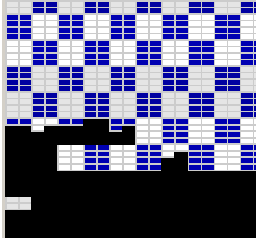 Figure 1: Tiles “curtain” filing pattern |
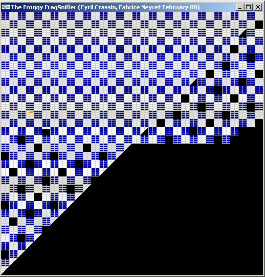
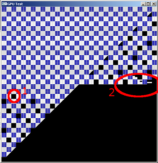 Figure 2: A tile containing a very slow fragment (1) makes all next tiles scheduled on the same TP to wait. Others TPs continue their processing until their fragments FIFO is empty (2).
|
E1.1: We make all fragments slow.
E1.2: We make one fragment a lot slower.
E1.3: We handle 2 very slow fragments, corresponding to 2 different slow branches of a conditional statement.
E1.4: We handle 4 very slow fragments, corresponding to 4 different slow branches of a conditional statement.
E1.5: 32 slow fragments running the same shader in the same neighborhood.
* Observations:
– The two quad triangles are draw one after the other (the triangle diagonal is strictly respected) .
– The left triangle is drawn in left-right ping-pong scanline while the right triangle is drawn in classical scanline.
– (Note that if another window hides a part of our window, the hidden part of the scanline is done at cost 0).
– Scanline is made at the granularity of 16×16 “tiles“, 2 rows of tiles at a time.
– Tiles are filled progressively through a “curtain effect” made of horizontal segments (see Figure 1).
– Tiles and their “curtain segments” are drawn in parallel and asynchronously along this “thick” scanline.
– When “blocking” one fragment with a very long shader, 16×16 black tiles appear every 6 tiles in rasterization order starting with the tile containing the blocked fragment (see Figure 2). These tiles are totally black but the first.
– Tiles are relative to the screen (not to the window, thus our alignment of the window location).
– In the first blocked tile 8×4 “sub tiles” appears (the “horizontal curtain segments”), organized in the tile as 2 columns of 4 subtiles (see Figure 3). The first blackened subtile is the one containing the slow fragment (or sometimes the one before), then the followings.
– After a few lines of drawn tiles with 1 missing every 6 tiles, all tiles get blocked as long of the slow fragment has not terminated its execution (see Figure 2).
– The board auto-resets and flush the pipeline if the drawing of the quad is not no finished before a timeout of 8-10 seconds.
E1.3: Using 2 slow pixels and cost 0 for other fragments .
Let’s call T the duration of each of the conditional branches these 2 pixels correspond to.
– If the two pixels fall in different tiles, total frame cost is T
– Except if these are tiles Ti and Ti+6j in raster order in which case it is 2T (for small j)
– If the two pixels fall in the same subtile, total frame cost is 2T
– If the two pixels fall in different subtiles of the same tile, total frame cost is T
(with a surcost of about 10% for vertical neighbors instead of horizontal neighbors) (1)
Same, taking care of writing shaders with no wait state[*1] (e.g. result of additions not needed for the next instruction):
– If the two pixels fall in different tiles, total frame cost is T
– If the two pixels fall in the same subtile, total frame cost is 2T
– If the two pixels fall in subtiles in different column of the same tile, total frame cost is T (2)
– If the two pixels fall in subtiles in same column of the same tile, total frame cost is 2T (3)
E1.4: Using 4 slow pixels and cost 0 for other fragments (see Figure 5).
– If the four pixels fall in different neighbor tiles, total frame cost is T
– If the four pixels fall in the same subtile, total frame cost is 4T
– If the four pixels fall in the same column, total frame cost is 4T
– If the two pixels fall in a column (either in the same subtile or not) and two in the other, total frame cost is 2T
E1.5: Using 32 slow fragments running the same shader in the same subtile: total frame cost is T
* Conclusions:
– For large primitives, fragments are scheduled on multiprocessors grouped by tiles of 16×16 pixels aligned on screen coordinates.
– One tile is treated by a TP, i.e. a pair of MP.
– tiles are allocated to MP depending only of their screen location (1 every 6 rasterized tiles, even if MP load is unbalanced).
– The pattern of allocation of tiles is presented of Figure 3 (it was obtained using a test not described here). It can be formulated as Tile(i,j)=(i-i0+N(j-j0))%6 with N(j)={0,2,4,1,5,3}[j%6]. Note that it ensures a distance of 6 between mappings of the same tile horizontally or vertically, and of at least 4 in L1-distance in any direction.
– Inside a tile, fragments are scheduled in 8×4 subtiles[*2] corresponding to warps of 32 threads. 32 threads in a warp run in parallel [*3].
– The subtiles of one column[*2] is run by one MP and the other ones by the other MP in parallel. (cf (2) vs (3)).
– Subtiles in a column are run in sequence.
– The fact that all MP get blocked after a few lines waiting for the termination of the slow fragment seems to be due to a synchronization issue. We think that the rasterizer fills per-TP FIFO buffers. When one FIFO is full (due to the busy MP calculating the slow fragment) the rasterizer stops feeding the FIFOs. Once all non-blocked MP have consume their FIFO they starve: the G80 stalls until the slow fragment calculation finishes. See the general scheme on Figure 4.
* Notes:
[*1]: Internally, one given shader instruction takes time to calculate (11 cycles), which is hidden thanks to the the internal SP pipe-line (ideally, one result per cycle). If an instruction yields a wait state (texture access, transcendent function call, use of a result just calculated) this would waste cycles. Instead, the MP processes the next warp during this spare time. Thus, 2 warps can seem to be evaluated in parallel. It is not the case if the shader has no wait state (thus (1) vs (3)).
 Figure 6: Oh, a warp ! |
[*2]: We will see later that this organization in 8×4 subtiles (packed in two columns) is only valid for this very experiment with an ideal primitive filling all the tiles. More generally, warps contain 32 fragments coming in order of rasterization (see Figure 6) and can be executed on any of the two MP of the pair.
[*3]: A reminder that a G80 has only 8 SP per MP so that only 8 threads are run in parallel at the silicon level. But 32-thread warps are considered at low-level by processing each given instruction on 4 threads in a row per SP. This is like emulating a 32-SP multiprocessor running 4 times slower. Note that it is not threading as in [*1].
[*]: In Cuda threads are grouped in rigid blocks allocated to a given MP. We wonder where they map here: tiles ? FIFO ?
In the following, we always use shaders with no wait state.
 |
 |
 |
 |
 |
|
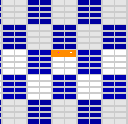
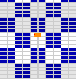
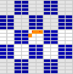
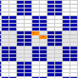
Figure 5: Different blocking pixels (in red and yellow) configurations and resulting blocked warps (in orange)
E2: Smaller and micro primitives
We draw smaller screen-aligned quads (or triangles) tiling the screen. We test different sizes and configurations and we measure the total rendering time for a frame.
E2.1: The cost of “background fragments” is set to 10^5 loop iterations.
E2.2: We introduce one slow pixel which cost is set to 10^6.
* Observations:
E2.1:
– One big (clipped) triangle covering all screen: 1.17s (= reference time).
– Small quads drawn on raster order :
– size 64×64, 32×32, 16×16, 8×8 = 1.5s (ref time+~25%), 4×4=6.78, 1×1~=9.96 (8x ref time)
– for sizes smaller than 16×16, raster order within 16×16 then raster order within the window:
– size 8×8: same cost.
– Quads translated by 1 pixel horizontally.
– size 64×64, 32×32, 16×16, 8×8 = 1.85s (+25%+25%), 4×4=7.82
– Two non-stripped triangles instead of quads: same timings.
E2.2:
– Concerning the pattern of black tiles and the FIFO stalling:
– For tiles >16×16 the behavior is as E1.
– For tiles < 16×16 the pattern is obfuscated due to the small size of drawing primitives. Still, the “mod 6” MP allocation and the FIFO stalling behaves the same.
– The number of tiles which can be drawn before stalling while one MP is blocked decrease together with quad size.
– If quads are grouped in sets of GL_Begin…GL_End drawing batch, the drawing of all MPs seems to wait the end of a batch before starting the next one (otherwise visual synchronization occurs only at FIFO stall as before). Looking at the performances, it does not seems that all MPs always wait.
* Conclusions:
– Type of triangles connection (strip vs nostrip) has no impact on pattern and on performances: it seems that no special optimization if done for strips so that they are considered as separate drawing primitives. for instance, a quad is considered as 2 separate triangles. This yields some waste, see discussion in [*4] at the end of the next section.
* Unexplained:
– Scheduling through MPs is done per drawing batch (glBegin…glEnd). A partial synchronization is done at the end of the batch. We do not understand the partial impact on performances.
– The +25% extra cost is logical for 8×8 quads: it corresponds to the filling of superfragments along the diagonal of the two triangles which doubles the number of diagonal superfragments.
Same thing for the the extra +25% for the 1-pixel translation: One fragment row of a new quad (bad parity alignment) enters the tile, which doubles the row superfragments.
But why these results for other sizes ?
Now we want to test the scheduling with less organized primitives: lines and points.
A remainder that reference time corresponds to one single triangle covering the screen.
E3: Lines drawing
E3.1: We draw horizontal lines filling the screen from bottom to top.
E3.2: We draw vertical stacks of lines (“pseudo-quads”) from left to right and from bottom to top.
* Observations
– 2x the reference time for lines of length 512.
– Lines split in segments of length 32, 16, 8, 4: same cost.
Length 2: cost +125% (4.5x the ref time)
– “Pseudo quads” of size 256, 128: same cost.
– “Pseudo quads” of size 64: +8% size 16, 8, 4: +18% size 2: +125% (4.5x the ref time)
Size 1: +360% (9x the ref time).
* Conclusions:
– Only half of all SPs in a warp are used because vertical neighbors are not part of the same line primitive and thus cannot be evaluated by the neighbor SP. [*4]
E3.2:
– Our hypothesis is that huge number of drawing primitives drawn at the same time may occasionally starve the other MPs and thus decrease the performances.
* Notes:
[*4]: DDX and DDY uncentered derivatives are obtained at no cost by combining values of the target variable evaluated at odd&even 4 neighbors. This yields that all “parity-neighbors” vertically and horizontally must belong to the same primitive (e.g. triangle or line). If these neighbors were not rasterized (considering the very same primitive), they are stored and calculated anyway for this very reason, forming an asymmetric “parity-bandguard” of 1 pixel. This impacts small primitives such as points (see next section), lines, micro-triangles, but also very probably contiguous larger primitives such as triangles in a mesh or in a quad (which pixels seem neighbor but cannot be recognized as such and thus cannot be let neighbor in the warp). We were expecting to see this only for non-stripped data, but performances and patterns are identical either stripped or non-stripped. So our hypothesis is that threads are *always* spoiled due to the parity-bandguard, which probably explains the lower performances for small primitives.
E4: Points drawing
E4.1 “Raster-bloc” of points: We draw points in lines from left to right and from bottom to top.
E4.2 “pseudo-quads” of points: we “raster” quads with points, then screen with pseudo-quads.
* Observations
– Blocking a given point (with a very slow shader) shows a block of 4×1 pixel sub-tiles (instead of 8×4 for large triangles).
– Very few tiles drawn before a FIFO stall (when blocking a fragment).
– raster: 8x the reference time.
– pseudo-quads of size 128, 64, 32, 16: timing progressively increases up to 83% for size 16.
– pseudo-quads of size 8,2, 1: 8x the reference time.
* Conclusions
– Warps seems to be only filled only with 4 points, thus the slowdown.
– FIFO seems less efficient for small drawing primitives: the smaller the primitive, the less pixels drawn between pixel blocking and MPs stalling. We believe that FIFO elements correspond to pre-assembled warps. Warps are less efficients when a lot of superfragments are filled with gosh fragment. Moreover, warps can host only 4 points.
E4.2:
– Our hypothesis is that huge number of drawing primitives drawn at the same time may occasionally starve the other MPs and thus decrease the performances.
*Unexplained:
– Bandguard-alignment should limits to only 8 points (instead of 32) per warp due to the 4×4 superfragments, see [*4] in previous section.
So, why do we get only 4 ? Might it be that superfragments are in facts 4×2 ? This would also explain some timings, but would contradict other ones.
E4.3: Spaced points. We draw points spaced by n pixels in each directions.
We measure the average duration per point as compared to the E4.1 “raster-bloc” as reference.
E4.4: overdrawing points.
We draw 512^2 points at the same pixel location and compare to the ref (on 512×512 points).
E4.5:
We draw 512^2 points cycling between 6 given different pixel locations falling on different TPs.
* Observations
– n=2,3,4,5,7,8: cost per point / ref =-3%, +8%, +0%, +5%, +16%, +10% (1)
– n=16: +35%
– Blocking a given point (with a very slow shader) shows 4×1 points sub-tiles.
– E4.4: cost: 6.1x the ref (2)
– E4.5: same cost than the ref (3)
* Conclusions
– Perf of (2) is due to the fact that only one TP is used. But both of its MPs are used, proving that these do not correspond to columns.
– “Holes” in tiles (1) or superimposing points (3) do not change performances too much (roughly):
warps seem to be filled sequentially with points, independently of their location in the tile or even in the following tiles mapped on the same MP.
– As mentioned in [*2] we believe that this is probably the general mechanism, even for large primitive (in which case the location coherency within a warp is simply due to the order of fragments rasterization).
– Note that all size 1 primitives (quads, triangles, lines, points) consistently cost the same: 8x the reference time (still, we do not understand why it is not 4).
5. Examples of recommendations
Here we present some unoptimal situations due to the behaviors we have presented above.
We suggest some idea on how the same drawing could be organized differently so to avoid the performance breakdown. The main purpose is to illustrate how different organizations and representations impact performances: these are not deeply tested universal recipes, don’t apply them blindly ! They are meant to trigger ideas on how to organize your drawing algorithm differently.
In particular, our tests were done on artificial shaders with no texture or memory access and saturating the pipeline. Some solutions good for such shaders might be very bad for shaders using intense memory access. For instance, shuffling locality in order to group similar tasks or to scatter costly tasks might be disastrous in terms of cache miss.
Some typical unoptimal situations correspond to:
5.1 Numerous primitives: no parallelism
If each drawing primitive is a different drawing batch there is a loss of performance due to a (partial) synchronization of all MPs.
5.2 Poor use of SPs due to excess of “band-guard” threads
This typically occurs with micropolygons (e.g. size 1 to 4) and points. Overcost is typically x8.
A solution is to rely on deferred shading: this allows to fill warps with 32 threads really corresponding to pixels.
5.3 Poor warp parallelism: one costly shader scattered on screen
E.g., Let suppose a sky-night textured on a sky mesh, with a fancy shader to run at stars. (e.g.: if the intensity of the current texture pixel is above a threshold then a dynamic branching occurs to run a complex blinking). Let’s assume the sky image is densely populated with N stars, and that the shader costs T for a star.
If each warp contains only one star, it costs the price of a star (no benefit of the 31 other SP). Total cost: NT/12
(parallelism through the 12 MP, no parallelism for stars in a warp or between warps or the same MP if the pipeline is saturated – note that in practice it is generally not the case so some gain occurs).
Some other ways to draw this sky-night texture could be:
– Drawing stars with point primitives separately instead of included in the sky texture map: would allows to group 4 of them per warp.
– Using the sky texture as a mask and do 2 passes: draw first only star pixels then background pixels. (Such a mask must generate only the target pixels. This can be done using features such as early depth test).
This should also gain 4.
– Pre-packing star texture pixels together and relying on an indirection map to encode the sky. Then do 2 passes: shading first the star block, then rendering the object mapped with the indirection texture. This should allow a gain closer to 32.
Now let suppose a texture with 2 different scattered fancy shaders. Let each cost T. We now have a total of 2N stars. Let assume that we have N wraps containing 2 stars.
The fragment shader paints background texture pixel, a type 1 star or a type 2 star through different branches in a conditional statement. These cannot run in parallel in a warp due to SIMD (divergences during conditional or dynamic branchings are serialized).
Using type 1 for all 2N stars, if each warp contains two stars it costs the price of one star. Total cost: NT/12.
If each warp contains one star of type 1 and one of type 2, it costs 2T. Total cost: 2NT/12.
Drawing all type 1 stars then all type 2 stars using point primitives or stencil mask would gain 4 as in the previous case.
5.4 Poor load balance of MPs
– If one MP has more work than the other ones, he will finish later: the 11 other MPs will starve at the end of the drawing batch.
If the drawing batch was very big (i.e. very larger than 1500 pixels) this will probably have low impact on the total cost, but not for smaller ones.
– If one MP has a lot more work than the others: the FIFO will probably stall most of the time so that only one MP will be working. Still, it is not very likely to occur due to the scattered pattern of tile/MP mapping (see Figure 3).
– For a scattered very costly shader (like in 4.3) falling statistically on any MP, the effect on performances dramatically depends on the density as compared to the “FIFO window” (about 5000 pixels with our shader when drawing a large primitive):
– if several MPs are impacted by stars then this tends to balance the load.
– if only one MP is impacted the others will starve: Total cost for the “FIFO window” will be T instead of T/12.
– if one MP is impacted twice in the FIFO window, the general starvation will late twice.
5.5 Killing the parallelism: unique shaders poorly scattered on screen
E.g., ray-tracing relying on the traversal of some acceleration structure. Rays passing close to the silhouette of an object will traverse the worst of the structure without being stopped. The cost of these pixels is thus a lot more than any other fragment. The precise work for each very silhouette ray is unique. They are rather scattered on screen, but grouped along the silhouette curve. (All this is even worse with transparency or volume ray-tracing since silhouettes are thicker).
If one wants to implement such algorithm in a shader on GPU, we have a combination of bad cases 5.3 and 5.4:
– A silhouette pixel might stall the whole FIFO.
– Several silhouette pixels are likely to fall in the same tile (and impact one single TP): stalling is even longer.
– These are even likely to fall in the same warp. Since the shaders for these pixels have different lives they are not running in parallel: their costs add, and so as the duration of the whole starvation.
Let suppose a vertical silhouette line of 16 pixels within a tile: This adds a cost of 16T to the rendering of the FIFO window. This is just like having one SP instead of 128.
Thus in addition to being a lot more costly to render by themselves, silhouette pixels can have an overcost of 128 due to the starvation of the whole G80 but one SP.
A solution consists in detecting and re-scheduling very costly unique fragments.
Still, the MP which will manage a given fragment is totally determined by fragment location on screen.
Thus the only two solutions are:
– Better balancing the costly shaders in time:
– E.g. grouping & rendering them in a separate pass using point primitives. This will make heavy cost for warps, but well balanced through MPs so that the FIFO should not stall.
– This could also be done with a stencil mask and two passes.
– If the poor scattering still yields an unbalanced load, we can balance the load by adapting the drawing order of points (custom FIFO).
– Cheating the tile/MP mapping:
Let’s assume a single TP was impacted in a FIFO window: the purpose is then to find how we can share the work with some other TPs.
– Drawing some of the costly pixels elsewhere on screen (so as to reach another tile) then copying+blending back.
– Could also be done with portions of each long shader.
– Drawing in several target buffers (FBO), using different spatial offsets (i.e. tile offset) for each buffer. Offsetting can be implemented by calculating in (i,j) the value targeted at pixel(i+di,j+dj).
– Using a dither pattern as a mask to draw some costly shaders in buff2 instead of buff1:
pass1: if (!mask(i,j)) buff1:=shader(i,j);
pass2: if mask(i-16,j) buff2:=shader(i-16,j);
then copy+blend buff2 on buff1.
– Split shaders: if shader was Part1(i,j)+Part2(i,j) both costly, use instead
pass1: buff1:=Part1(i,j);
pass2: buff2:=Part2(i-16,j);
then copy+blend buff2 on buff1
March 20th, 2008 on 4:13 pm
so fancy job! att, you must have been working in gpu industries, since you easily mention many recondite jargons..